Helical cross sections
The average cross section of a filement with known cross-overs can be calculated by reconstructing the 2D projection following the helical twist. The requirements are that the filament lies parallel to the y axis and in the center of the image.

Projection of an artificial helix with a rise per subunit of 40 Å and a rotation per subunit of 66°.
A cross section can be calculated from this filament image:
Cross section.
The cross section is intended to enhance the signal along the filament axis. Two measures are provided to estimate the signal-to-noise ratio (SNR) in the cross section. The first (option -snrradius) is a simple division of the image into a disk with a given radius in the center representing signal plus noise (foreground), and the surrounding area representing only noise (background). The SNR is then the relationship between the power (variance) in the foreground and the power (variance) in the background:
SNR = foreground/background - 1
The second measure (option -kernel) calculates the local variance within the kernel of the given size, divides the variance histogram into foreground and background areas, and estimates the SNR from the average variances in these regions.
The cross section can be aligned to a reference image by cross correlation using the alignment options.
A 3D volume can be calculated from the cross section by extrusion:
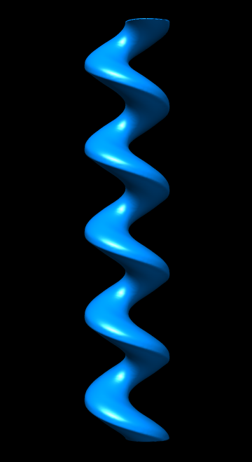
An extruded cross section