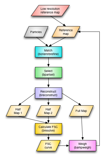
Single Particle Analysis - Resolution-limited version
1. Background
Limiting the resolution considered for aligning the particle images aims at using only high-quality information in the reference map. The low resolution limit cuts out low frequencies with little orientation information but strong intensities. The high resolution limit excludes high frequency noise that could compromise the alignment. When the resolution of the reconstruction is determined, significant information beyond the high resolution limit used should be apparent. If the FSC curve drops close to the high resolution limit, it is likely that the images are noise images or that the reference used is inappropriate.
The reconstruction from one iteration of alignment is typically used as reference for the next iteration. The high resolution limit should be chosen based on the FSC curve associated with this reference map. A typical choice is the resolution where the FSC curve is still above 0.7 or 0.8. This guideline can be used to automatically pick the high resolution limit.
2. Preparation
The preparation for this workflow (CTF fitting and particle picking) is the same as for the typical SPA. The descriptions for orientation determination and reconstruction also apply, with the exceptions noted below.
3. Determining particle orientations
A reference map consistent with the size of the particle images is required. This map can be from a previous reconstruction of the same type of particles, a map generated from an atomic structure, or a synthetic map generated from geometric shapes (see the Synthetic Map part for more information).
There are two programs for particle alignment: borient and brefine. borient does a global search of orientations in the asymmetric unit while brefine improves the already existing orientations locally.a. borient:
For each run of orientation-finding, create one directory such as run1, run2, etc. Change to the next run directory and launch borient to determine particle orientations:
borient -v 1 -sym D5 -angle 2 -resol 25,150 -ann 10,90 -mode ccc -CTF -ref klh_ref.pif -out klh_run1.star ../klh_ctf.star > klh_run1.log &
Depending on the particle size and the search grid (determined by the option -angles), this can run for a long time (smaller angles mean more projections and longer runtimes).
The algorithm in borient determines the orientations of the particles using a reference-based projection-matching algorithm. Projection images are produced from a reference map for all views within the asymmetric unit for the specified point group. For every comparison of a particle image to a projection image, the best matching in-plane rotation angle and the best particle origin are determined. The in-plane rotation matching is done by using polar images of both the projection and the particle. Because this is dependent on the origin if done in real space, the first determination of the in-plane rotation angle is done on polar power spectra of the projection and the particle. The projection is rotated by the in-plane rotation angle and cross-correlated with the particle to find the first estimate of the origin. This provides a reasonable origin for generating the polar image of the particle, which is then used to find the next estimate of the in-plane rotation angle. The origin and angle determinations are done iteratively until the result stabilizes (typically only 2-4 iterations). The projection image giving the best correlation coefficient for a specific particle image determines the view parameters for that particle. The key parameters are the angular increments between views (option -angles; typically 0.5 – 3˚), the annuli used for the real space polar image matching (option -annuli; usually include the whole particle image) and the resolution limits for reciprocal space polar image matching and cross-correlation (option -resolution). A particular range of annuli can be specified for determining the in-plane rotation angle, allowing exclusion of especially the center of the particle which may not contribute to an accurate determination of this angle.
The output from orientation-finding is a new parameter file with the following new parameters for the best fit of the particle images to the projection images:
- Particle origins
- Particle views
- FOMs: Figures-of-merit based on the correlation coefficient for the bets fit
- Projection index for the best fit: this appears in the selection
column
The orientation-finding should only be run once per reference map, because the existing parameters in the input parameter files are not used in subsequent runs. (The reason is that iterative refinement has already been incorporated in borient and multiple runs on the same reference map will just give the same results.)
b. brefine
After a previous run to find the rough particle orientations in the asymmetric unit, brefine can be used to improve the orientations locally. It is run the same way as borient, typically in a new directory:
brefine -v 1 -grid 2,0.2 -res 20 -mag 0.03 -defocus 0.002 -kernel 6,2 -ref ../run1/klh_run1.pif -out klh_run2.star ../run1/klh_run1.star > klh_run2.log &
The refinement algorithm runs in reciprocal space, extracting a central section from the Fourier transform of the reference map with kernel-based interpolation. The central section is then compared with the particle transform and a figure-of-measure (FOM) calculated (-fomtype option) to the specified resolution (-resolution option). This comparison is repeated in a small grid around the current view, starting at an initial stepsize and contracting around the best solution to a minimum step size (the step sizes are the two values for option -grid). Refinement of the magnification can also be turned on, specifying the maximum adjustment in magnification to consider (-magnification option).
brefine can be run in a different mode:
brefine -v 1 -monte 10 -res 25 -defocus 0.002 -kernel 8,2 -ref ../run1/klh_run1.pif -out klh_run2.star ../run1/klh_run1.star > klh_run2.log &
Here the orientation parameters are adjusted using a Monte Carlo approach to find views close to the input that improve the FOM's. The more iterations are run (value for the -monte option) the more likely that good solutions will be found, but at the cost of longer runs. The extent of changes in this algorithm can controlled through the options -shift, -view and -angle.
4. Particle selection
The selection of particles for reconstruction can be done in several ways.
a. Particles can be selected by the correlation coefficients (FOMs) generated during orientation-finding:bpartsel -v 7 -all -fom 0.34 -out klh_run1_sel.star klh_run1.star
b. The FOMs are typically related to the defocus, and this can be used to select particles with a varying FOM cutoff based on a linear fit between the FOM and defocus values. This is turned on by adding a flag to the "-fom" option:
bpartsel -v 7 -all -fom 0.2,1 -out klh_run1_sel.star klh_run1.star
c. A given percentage of the particles ranked by FOMs can be selected:
bpartsel -v 7 -all -top 70 -out klh_run1_sel.star klh_run1.star
d. The FOM cutoff for selection can be based on the standard deviation of the FOMs:
bpartsel -v 7 -all -deviation -1.5 -out klh_run1_sel.star klh_run1.star
e. The FOMs can be ranked and grouped into sets of decreasing FOMs to be able to generate several reconstructions:
bpartsel -v 7 -all -rank 5 -out klh_run1_sel.star klh_run1.star
There are several other particle selection schemes that can also be used.
5. Reconstruction
The reconstruction can then be done from the selected particles. Typically, two maps from different halves of the selected particles need to be generated to determine resolution. These two maps can be added afterwards to give the full map. The program breconstruct has several options to do the reconstruction in different ways, depending on the desired outcome as well as the capabilities of the computer being used. Here are a few cases:a. A simple reconstruction:
The main decision is to what resolution the reconstruction should be calculated:
breconstruct -v 3 -resol 15 -rescale 0,1 -sym D5 -CTF baseflip -recon klh_run1.pif klh_run1_sel.star >& klh_run1_rec.log &
b. Two half set reconstructions and a full set reconstruction:
All three maps can be calculated at the same time:
breconstruct -v 3 -resol 15 -full -half -rescale 0,1 -sym D5 -CTF baseflip -recon klh_run1.pif klh_run1_sel.star >& klh_run1_rec.log &
The resultant maps from the half sets have the inserts "_01" and "_02" before the extension. These maps can be added to generate a single reconstruction that is the same as the full set map:
bop -v 7 -add 1,0 klh_run1_01.pif klh_run1_02.pif klh_run1.pif
c. Threaded reconstruction:
If Bsoft was compiled with OpenMP and FFTW3 support, the reconstruction can be run with multiple threads:
breconstruct -v 3 -resol 15 -full -half -threads 8 -rescale 0,1 -sym D5 -CTF baseflip -recon klh_run1.pif klh_run1_sel.star >& klh_run1_rec.log &
Be aware that this is very memory-intensive, requiring 20 times the map volume per thread. For example, a map of size 500^3 will require about 2.5 Gb per thread.
d. Selected reconstructions:
Reconstructions can also be done from specific selection numbers in the parameter file using the "-classes" option:
breconstruct -v 3 -resol 15 -full -half -classes 1,3-5 -threads 2 -rescale 0,1 -sym D5 -CTF baseflip -recon klh_run1.pif klh_run1_sel.star >& klh_run1_rec.log &
In this case the threads are per class, and for calculating halfmaps in each class, the number of threads should be even. Because of memory limitations, it is likely better to specify only one class per run.
6. Resolution determination
The two reconstructions are then compared to determine the resolution:bresolve -v 7 -resol 15 -align 25 -Post klh_run1_resol.ps -map klh_run1_01.pif klh_run1_02.pif
The -align option should indicate the resolution limit used in the particle alignment. The resolution curves for FSC (Fourier shell correlation) and DPR (differential phase residual) are written into the postscript file in such a way that it can be opened in a graphing program that can interpret text files (Kaleidagraph or Excel).
7. FSC filtering of reconstructions:
The FSC curve can be used to do an appropriate filtering of the reconstructions to more accurately represent the actual information content:
bampweigh -v 7 -FSC klh_run3_resol.xml -resolution 15 -rescale 0,1 klh_run3.pif klh_run3_fsc.pif`