Tomographic series fiducial-based alignment
The fiducial-based alignment algorithm attempts to predict where a fiducial marker image moves with a change in tilt angle. Because the major movement is perpendicular to the tilt axis, the tilt axis angle must be known to a reasonable degree of accuracy. The following workflow starts with defining a marker seed set in the zero-degree (or close to it) micrograph. The tilt axis is then determined, followed by marker tracking and refinement. The final product is a full 3D transform for every micrograph to place it within the same frame of reference.
All of this can be done automatically on the command line. However, the user must use some judgment in choosing the parameters for each alignment. These include the parameter sfor generating the power spectra and fitting the CTF. Sometimes the marker tracking fails for some micrographs, which then need to be corrected manually.
1. Generating seed fiducial markers
Open the parameter file in bshow and change to the zero-degree tilt micrograph. Make sure the marker radius is accurately set to half the diameter of a typical marker image. Select the menu item “Tomography/Find markers in current image”. This will cross-correlate a synthetic marker based on the marker radius with the image, and present a set of hits and a dialog box. Adjust the FOM slider in the dialog box until a satisfactory set of markers are selected and click on "Done".
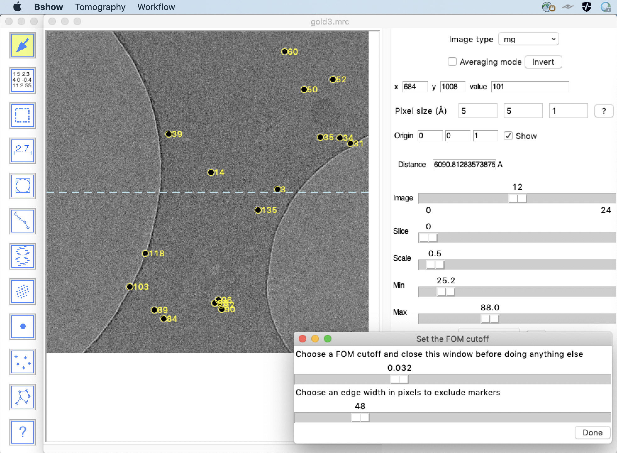
Markers can be added or deleted manually with the marker tool:
Eliminate markers that are close to edges, because they
might not stay within the frames of all the images in the series.
Markers that are clustered should all be selected because the
algorithm relies on cross-correlating the vicinity of every marker,
not just the marker.
Save the result to a parameter file using the menu item
"Micrograph/Write parameters".
2. Finding the tilt axis
The tilt axis angle is determined by how the camera is installed, as well as the magnification used. In modern electron microscopes the magnifications are chosen to avoid big rotations when changing magnification. Once the tilt axis angle is known for a particular microscope and magnification, it can be used as starting point for alignment. In Bsoft, the tilt axis angle is defined as the counterclockwise rotation angle from the x-axis to the tilt axis. To find the tilt axis angle to within acceptable accuracy, two methods are available. The first is a fast method potentially with less accuracy, and the second is slower and more accurate. Eventually, after proper tracking of the markers, the refinement of the micrograph orientations will give the best possible tilt axis angle. This axis angle can then be used for all subsequent tilt series obtained from the same microscope.
Note that the nominal tilt angles must already be specified.
2.1. Fast tilt axis determination
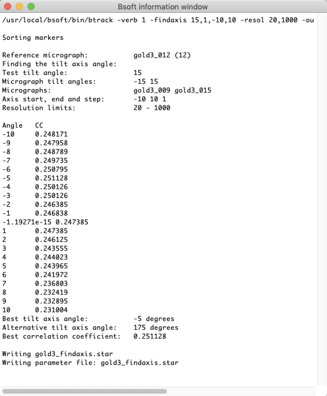
The program btrack offers a fast way to determine the tilt axis. The algorithm uses two micrographs closest to the positive and negative of the tilt angle specified. At each axis angle within the range specified, the seed markers are used to generate an image that has the distribution of markers expected. This is then correlated with the corresponding micrograph. The axis angle that gives the maximum correlation is taken as the correct one.
The following command line selects micrographs close to 15° tilt and with a tilt axis angle step size of 1° witin the range of -10° to 10°:
btrack -v 1 -findaxis 15,1,-10,10 -out gold3_findaxis.star gold3.star
The same command can be launched from within bshow using the "Workflow/Find tilt axis" menu item.
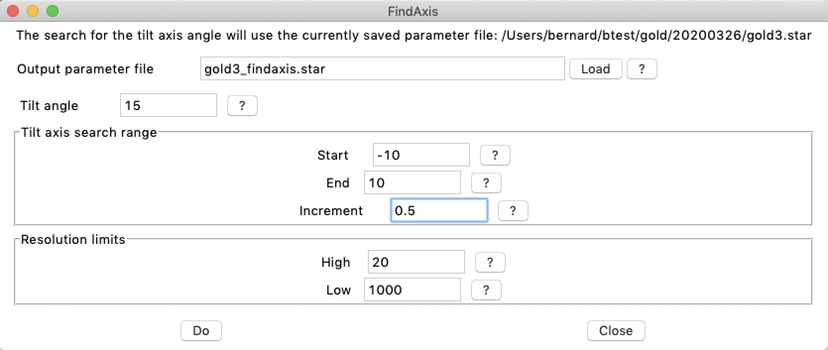
The output is written to a text window that can be saved using the "File" menu.
At this stage the results are not yet in bshow memory. Close the text window and click on the "Load" button in the "FindAxis" window to load the new parameter file in memory. The best tilt axis angle should now be displayed in the "Tomography" window.
2.2. The tomax script
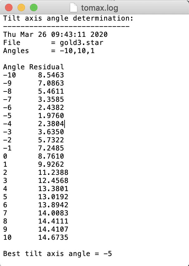
This script uses full tracking runs with different tilt axis angles to determine the best residual. It is very compute-intensive and should only be used if the faster method doesn't work. The tomax script is run specifying the initial angle, the angle step size, and the final angle to test for:
tomax -angles -10,1,10 gold3_seed.star
or:
tomax.pl --file gold3.star --start -10 --end 10
The output gives the residual for a single iteration attempt of tracking the markers at each tilt axis angle. The best (lowest) residual is reported and should be used subsequently.
Output from the tomax script:
3. Alignment: Tracking markers
The program btrack tracks the markers starting at the micrograph with the seed fiducial markers, usually one close to zero-degree tilt. The tracking proceeds from low to high tilt angles in both directions. For each micrograph, it generates an image containing all the markers at their current locations and considering the current tilt angle. This is then correlated with the micrograph to get the shift (which defines the micrograph origin). The z-coordinate of each marker is then determined by tracking along a line perpendicular to the tilt axis, cross-correlating with a marker reference image. This generates a z-coordinate for the marker for every micrograph in the tilt series. The actual z-coordinate is taken as the average of all the z-coordinates. The standard deviation of the z-coordinates is used as an indication of how well the marker location is defined. This process is iterated (typically 2-5 times) until the average change in z-coordinates drop below a set stopping condition (usually one pixel) or up to the maximum number of iterations. The combination of translations and rotations have an infinite number of representations. To restrict them to the most useful representations, the overall z-coordinates should be recentered after processing each micrograph. This keeps the micrographs within the same volume that will eventually become that of the reconstructed tomogram. Finally, the exact positions of the markers in each micrograph are then refined (-refine markers).
The tracking can be done from the command line or from bshow (see below). A typical command line is:
btrack -v 1 -exclude none -reset -update -track 1,1.5 -axis -5 -resol 20,1000 -recenter -refine markers -out gold3_trk.star gold3_seed.star >& gold3_trk.log &
The options used here are:
- The -exclude none option ensures that all the micrographs are selected.
- The -resetmodel option ensures that the zero-tilt marker positions agree with those of the 3D model at the start of tracking.
- The -updatematrix option recalculates the micrograph orientation matrices from the tilt axis and tilt angles.
- The -track option activates tracking and sets the maximum number of iterations and the target stopping condition.
- The -axis option sets the tilt axis angle
- The -resolution option limits cross-correlation. For high-intensity gold markers the relatively low resolution limit of 20 Å should suffice in most cases.
- The -recenter option centers the overal z-coordinates at every update.
- The -refine markers option adjusts the final locations of the markers by cross-correlation with a marker reference image.
The equivalent in bshow is done by selecting the "Workflow/Track markers" menu item:
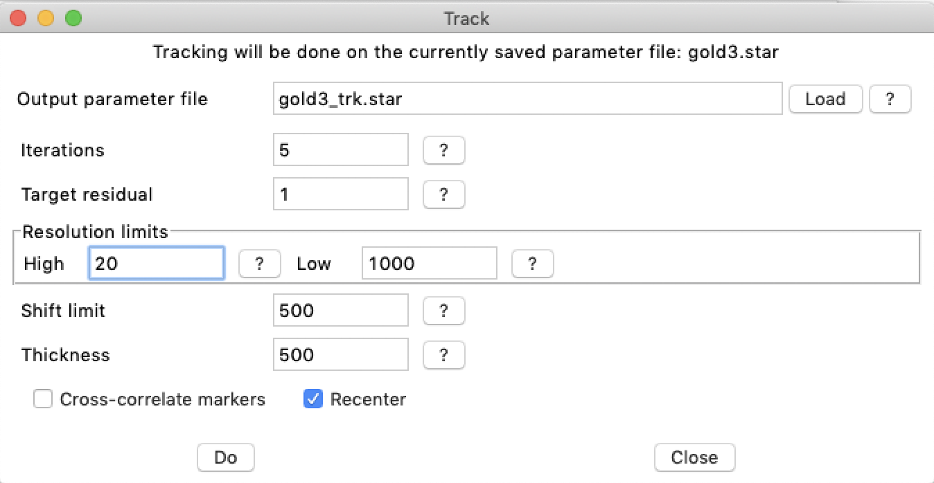
After every iteration a parameter file is written to allow for user inspection and trouble-shooting (file names gold3_trk_01.star, gold3_trk_02.star, ... ). To follow the progress in tracking, the log file can be queried:
grep Cycle gold3_trk.log
Cycle 1: Average change in positions = 35.8846
Cycle 2: Average change in positions = 0.440963
This gives the change in marker positions for every iteration, with the first always a high number because the z-coordinates are zero at the start. When the change in positions drop below the stopping condition, a reasonable alignment has been reached and the program finishes. Otherwise, the iterations continue up to the maximum specified. The overall residual is given at the end of the log file:
tail -2 gold3_trk.log
Average residual = 1.98881 pixels
The new parameter file can be read with bshow to examine the marker positions:
bshow gold3_trk.star &
If the tracking is done from bshow, the output parameter file can be loaded with the "Load" button in the tracking dialog window (see above).
4. Alignment: Fixing markers and refinement
The success of tracking varies because of intrinsic features in each tilt series. In the majority of cases the marker locations need to be adjusted manually to improve the alignment. In the bshow image display, the markers have orange lines, where each line indicates the difference between the current marker position and the position predicted from the 3D marker model. Markers with big deviations or those that are obviously incorrect, can be adjusted manually. For manual positioning, drag the marker until it fits nicely over the correct marker image. In some cases, the whole set of markers are offset. This can be fixed with the grouping tool:
Place the cursor on one marker and drag the whole set to coincide with correct marker images. To turn off the grouping behavior, select the pointer tool:
Select the "Tomography/Refine" alignment. This opens a dialog box with several options to improve the alignment:
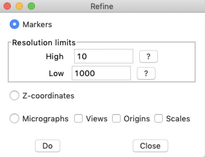
- Markers, which refines the marker positions on the micrographs
- Z-coordinates, which refines the 3D model z-coordinates
- Micrographs, which refines the geometry associated with each micrograph
- Views
- Origins
- Scales (be careful here, scale refinement may compensate for tilts and should only be done once and as the last refinement)
The top option is to refine the marker positions by cross-correlation. This is the same as the -refine markers option in btrack. Run this option once by clicking on the "Do" button. This will change the "Residual" value in the main "Tomography" window. This is typically be in the range of 1-20 pixels before any further refinement.
Next, select the "Z-coordinates" checkbutton and run it. Then select the "Micrographs" checkbutton, as well as the "Views" and "Origins", and run it. Both these should reduce the residuals. Run these two options alternately until the residual stay about the same.
The menu item "Tomography/Show marker table" and the "Marker table" button in the main Tomography window opens a table of markers. This table lists the markers with their associated FOM's and residuals. The buttons at the bottom allow the user to find the highest and lowest of each parameter, and step through the markers. The display in the main window will change to show the selected marker. Select the markers with high residuals and manually adjust them to positions that are correct by eye. Then click on the "Update" button to recalculate the overall residual displayed in the main Tomography window. Combine this with refining the Z-coordinates and micrograph orientations in the "Refine" window.
The refinement can also be run on the command line:
btrack -v 1 -reset -refine 10,z,o,v -out gold3_ref.star gold3_trk.star >& gold3_ref.log &
Once the overall residual is acceptably low (typically 1-3 pixels) and all markers are deemed to be in the correct locations, save the parameter file. The micrograph orientations are now appropriately specified for reconstruction. The algorithms in Bsoft are based on a general rigid-body target function with no restrictions on the view (such as assuming a tilt axis perpendicular to the electron beam), so that the final alignment can be used directly in reconstruction.
5. Trouble shooting
5.1. Marker reference images
If the overall residual remains high (> 5 pixels), there may a problem with how the alignemnet is done. The marker tracking and location refinement rely on a marker reference images produced as an average of the marker images in the zero-tilt micrograph. These images are written into the files "marker_track_ref.map" and "marker_refine_ref.map" for tracking and refinement, respectively. They should look something like this:

If they look significantly different from the example, please send me a bug report with all the details (bernard_heymann@nih.gov).
5.2. Manual marker positioning
If marker tracking completely fails, the markers can be manually positioned. To alleviate some of the manual labor required, markers can be generated from a seed in the zero-tilt micrograph, using the nominal tilt axis and tilt angles:
btrack -v 1 -generate -out gold3_gen.star gold3_seed.star
This can also be done in bshow using the menu item "Tomography/Generate markers from seed". The markers can then be correctly placed manually, poentially followed by the refinement steps aoutlined above.